 10/100BASE-T SFP
CS UPC Single Channel (2F) OS2 Fiber Adapter with Flange
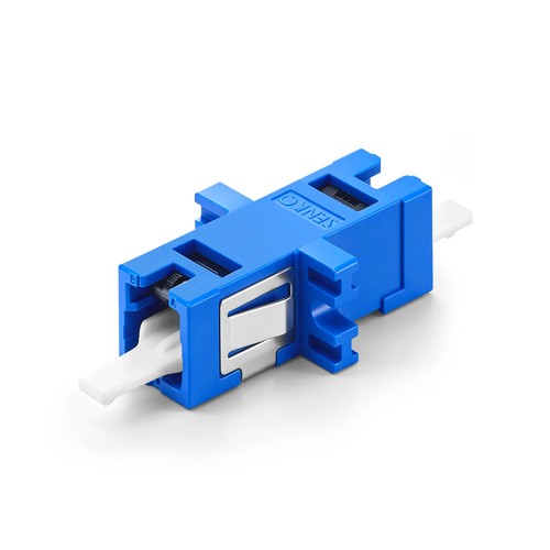
New Zealand engineering teams can use the documented values below to compare the product with the intended channel and as-built requirements. %s belongs to the very-small-form-factor generation of fiber connectivity. Compared with a duplex LC mounting point, the VSFF interface carries the matching two fibers in roughly half the relevant panel space, which is what makes 200G, 400G and 800G breakout panels physically possible at high port counts. The relevant adapter holds the ferrules aligned and latches the connection interfaces positively.
Product Highlights
- ≤0.2dB (Typical) Low Insertion Loss
- Color Coded for Rapid Identification of Single-mode Fiber Patterns
- Senko CS Reduces Connector Size by 40% Compared to LC Duplex
- Apply to 200/400G QSFP-DD, OSFP and COBO
- 2x Fiber Cabling Density over LC Adapters
Specifications
| Connector Type | Senko CS-CS |
|---|---|
| Body Style | Single Channel (2F) |
| Polish Type | UPC |
| Fiber Mode | OS2 9/125μm |
| Insertion Loss | ≤0.2dB |
| Durability | 200 times |
| Mounting Type | Full Flanged |
| Color | Blue |
| Flammability Rate | UL 94V-0 |
| RoHS Compliancy Status | Compliant |
| Operating Temperature | -40 to 85°C (-40 to 185°F) |
| Storage Temperature | -10 to 60°C (14 to 140°F) |
Phosphor bronze and zirconia sleeves compared
Two sleeve materials dominate the relevant adapter market. Zirconia ceramic sleeves give the tightest alignment and are the compatible alternative for single-mode and high-behavior multimode work, where core geometry leaves no room for eccentricity. Phosphor bronze sleeves serve legacy multimode and metallic-ferrule connectors where the tolerance requirement is looser and the cost matters more. Matching the sleeve to the application keeps the two behavior and budget under control.
Very small form factor connectivity
VSFF interfaces - CS, SN, MDC and MMC among them - exist given that the duplex LC became the bottleneck of panel density. A CS or SN mounting point carries two fibers in about half the LC duplex space, and an MMC carries sixteen in the space of a small module. The adapters that mount these interfaces hold the matching optical discipline as their larger ancestors: precision sleeves or guide-pin alignment, positive latching and keyed orientation. The reward is a panel that serves 400G and 800G breakout optics at full port count.
Planning a VSFF panel position
VSFF adapters belong wherever breakout optics meet the fiber plant: a 400G-DR4 transceiver breaks to four duplex positions, and at CS or SN density those four positions fit beside their neighbors without a larger chassis. Plan the relevant panel around the transceiver roadmap - the relevant adapter footprint follows the relevant connector, and the relevant connector follows the optics. Given that the format is new adequate that local stockists rarely carry it, keeping spare VSFF adapters in the site kit is cheap insurance,.
What adapter testing actually measures
Because an adapter contributes no signal of its own, its test is a mating test: reference connectors mate through the relevant adapter, and the inserted loss is recorded. A zirconia-sleeve adapter ought to add no more than 0.2 dB, and the mating must repeat that figure across cycles. Durability testing runs the mating hundreds of times and re-measures - a sleeve that wears loose announces itself as creeping loss. These figures, not the housing color, are what separates an adapter that serves for years from one that becomes the mystery fault.
Selecting the right adapter for the panel
Five decisions define the relevant adapter order: the relevant connector pairing must be compatible with the two sides of the mating, the mounting style must fit the relevant panel cutout, the polish color code must be compatible with the plant, the sleeve material must suit the behavior grade, and the count must cover the load-out plus spares. Getting all five right at order time is what turns a bag of couplers into a dependable panel. Where the pairing crosses connector families, the hybrid range covers the common conversions.
Optical Testing and Quality Checks
Each adapter is inspected before packing: the sleeve bore is checked for alignment and surface finish, the housing latches are cycled for positive engagement, and sample matings from every production lot are measured for insertion loss. Accessories are checked for fit against the adapters they serve.
How to Specify and Order
Refer to this adapter by connector pairing, mounting style, polish grade and pack quantity when requisitioning a quotation. For configurations outside the listed options - mixed packs, panel hardware kits or project packing - send the requirement with the enquiry and the factory will cross-check the manufacturable specification. New Zealand project orders can include documentation and labeling requirements alongside the technical configuration.
