 10/100BASE-T SFP
MDC UPC to LC UPC Duplex Push-Pull Boot Uniboot OS2 Fiber Patch Cable
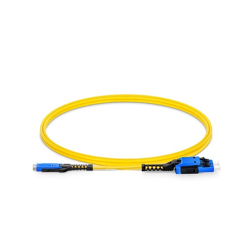
New Zealand engineering teams can use the documented values below to compare the product with the intended channel and as-built requirements. This OS2 fiber patch cable carries a MDC UPC interface on one end and a LC UPC interface on the other, factory terminated on OS2 glass and optically tested as a full item. The uniboot design places the two fibers of the duplex optical path inside a single round 2.0mm cord with one combined connector housing, halving the relevant cable count in high-density panels and simplifying polarity management.
Product Highlights
- Uniboot Allows One Cable to Carry Two Fibers to Reduce Cable Congestion in High Density Patch Fields
- G.657.A1 & 10mm Min. Bend Radius
- 3x Fiber Cabling Density over Duplex LC, Providing 432 Fibers within 1 RU
- DirectConec™ Push-pull Boot for Effortless Connector Insertion and Extraction
- Simple Polarity Reversal with No Exposed Fibers
Specifications
| Connector A | US Conec MDC UPC Uniboot |
|---|---|
| Connector B | LC UPC Uniboot |
| Insertion Loss | ≤0.3dB |
| Return Loss | ≥50dB |
| Fiber Mode | OS2 9/125μm |
| Wavelength | 1310/1550nm |
| Attenuation at 1310nm | ≤0.4dB/km |
| Attenuation at 1550nm | ≤0.3dB/km |
| Fiber Grade | G.657.A1 |
| Fiber Count | Duplex |
| Cable Outside Diameter (OD) | 2.0mm |
| Tensile Strength | (Long/Short Term) |
| Polarity | A (Tx) to B (Rx) |
| Operating Temperature | -10 to 70°C (14 to 158℉) |
| Storage Temperature | -20 to 70℃ (-4 to 158℉) |
Bend tolerance in real cabinets
Patch fields are rarely kind to fiber. Patch leads channel through tight managers, sharp tray corners and crowded vertical channels. The bend-insensitive glass in the supplied assembly tolerates a 10mm fiber bend radius; therefore, a hurried routing decision during a night service work window does not on its own turn into a measurable penalty on the optical path.
Where single-mode jumpers earn their place
Single-mode patching carries the links that leave the room: campus backbones, carrier handoffs, long runs between buildings and each wavelength-multiplexed service. The OS2 glass in the supplied assembly is the matching section used in the outside plant; therefore, the relevant jumper does not on its own become the weak point of the loss-budget calculation. At 1310 and 1550nm the attenuation stays a fraction of a decibel per kilometer, and the relevant connector pair adds less than 0.3dB when the end faces are clean and seated.
One cord, two fibers
The uniboot design merges the duplex pair into a single round cord and a single connector housing. In a 400G row where each QSFP-DD port consumes a duplex optical path, halving the cord count visibly changes the airflow and the manageability of the patching field.
Length Options
Regular length versions cover the common patching routes: 1m (3ft), 2m (7ft), 3m (10ft), 5m (16ft), with made-to-order length offered beyond the list. Specifying the measured channel length keeps the slack out of the manager and the strain off the connection interfaces.
Quality Control and Testing
Each optical assembly is terminated with precision zirconia ferrule connectors and optically tested before packing: insertion loss and return loss are verified on every cable, and end-face geometry is inspected for consistent physical contact. The relevant cable ships with dust caps on the two connectors and the test result offered on specify.
Ordering and Factory Support
Refer to this design by connector pair, fiber mode and length when requisitioning a quotation. For configurations outside the listed options, mixed connector families, jackets, identification or project packing, send the requirement with the enquiry and the factory will cross-check the build before production is released. New Zealand project orders can include documentation and labeling requirements alongside the technical configuration.
