 10/100BASE-T SFP
Cisco OSFP-800G-2QAE Compatible 800G Twin-port OSFP 8 x 100G PAM4 IHS/Finned Top to 2 x 400G QSFP112 4 x 100G PAM4 Active Electrical Breakout Cable
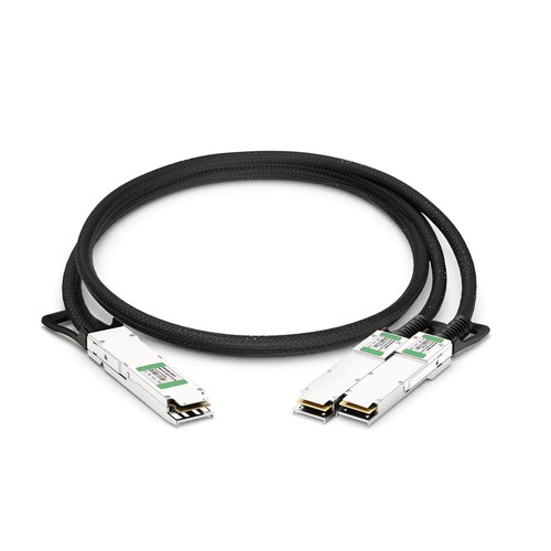
The OSFP-800G-2QAE compatible series is designed for Cisco hosts requiring a 800G AEC connection. Its OSFP (IHS/Finned Top) to 2x QSFP112 arrangement is supplied as an active electrical assembly intended for hosts supporting the stated retimed interface. Use the specifications to assess the physical assembly, then follow the exact length and part-number links when preparing a bill of materials or requesting a compatibility check.
Series Part Number: OSFP-800G-2QAEHT Part Number: OSFP-800G-2QAE
Product Highlights
- HT-manufactured compatible alternative for Cisco OSFP-800G-2QAE
- 800G aggregate connectivity at 800Gbps
- Interface configuration: OSFP (IHS/Finned Top) to 2x QSFP112
- Active Breakout DAC (AEC) / Copper
- Length configurations covered: 5m (16ft)
- Conductor specification: 28AWG
- Power consumption: 12W (OSFP End)7.5W (QSFP112 Per End)
- Operating temperature: 0 to 70°C (32 to 158°F)
Available Lengths and Corresponding Part Numbers
The documented series configuration is 5m (16ft). Use the relevant OEM reference below together with the HT identity and required length when requesting a quotation. If another length carries a different OEM part number, it must be reviewed and ordered as that distinct configuration.
Compatible OEM Part Numbers
- OSFP-800G-2QAE05
Specifications
| HT Part Number | OSFP-800G-2QAE |
|---|---|
| Manufacturer | HT |
| Form Factor | OSFP (IHS/Finned Top) to 2x QSFP112 |
| Max. Data Rate | 800Gbps |
| Media | Copper |
| Cable Type | Active Breakout DAC (AEC) |
| Cable Length Options Covered | 5m (16ft) |
| Jacket Material | PET |
| Minimum Bend Radius | 38mm |
| Wire AWG | 28AWG |
| Max. Power Consumption | 12W (OSFP End)7.5W (QSFP112 Per End) |
| Modulation Format | OSFP-8x 100G-PAM4QSFP112-4x 100G-PAM4 |
| Commercial Temperature Range | 0 to 70°C (32 to 158°F) |
| Application | 800G/400G Ethernet |
| Protocols | CMIS 5.0, IEEE 802.3ck, OSFP MAS Rev5.0, SFF-8679 |
Applications and Deployment
Active electrical cables use signal recovery or retiming to support demanding high-speed electrical links. Deployment should begin with host support for the exact AEC configuration, followed by checks of per-end power, cooling and breakout operation. The two ends and cable are engineered and tested as one assembly. For this series, the listed interface is OSFP (IHS/Finned Top) to 2x QSFP112 and the aggregate rate is 800G. The stated application is 800G/400G Ethernet.
Cisco Compatibility and Factory Testing
Verification covers the physical connectors, expected host identity and an operating link with available diagnostic indications. We distinguish this complete check from a simple continuity test. Platform model and software release can be reviewed in advance where the installation has strict documentation or change-control requirements. Series-level inspection is followed by the exact length and OEM configuration selected for dispatch. Functional verification includes link establishment and diagnostic indications where the host exposes them.
Cable Construction and Routing
For this assembly, the conductor specification is 28AWG; the jacket material is PET; the minimum bend radius is 38mm; the operating temperature is 0 to 70°C (32 to 158°F); the power consumption is 12W (OSFP End)7.5W (QSFP112 Per End). These parameters belong in the installation review rather than being treated as catalogue trivia. Route the cable through its intended managers without tension, avoid pressure close to the connector boots and leave enough space to operate the latches. Any service loop must respect the stated bend limit.
Structured Pathways and Serviceability
Treat the direct-attach assembly as part of the permanent pathway plan even when the link is expected to be temporary. Follow the intended horizontal and vertical managers, maintain the specified bend radius and leave service access around both ports. A small, supported service allowance is preferable to excess slack concealed inside a rack or placed under cable-tie pressure. For this series, keep the interface rate, AEC construction and length-specific OEM reference together throughout that review.
Ordering Information
Include the part number, fixed length, quantity and required pathway or rack grouping in the order information. The host model and firmware release are useful for change-controlled deployments. Different lengths should remain separate order lines so delivered labels and packing records agree with the pathway plan. For this series, follow the corresponding length link, quote that exact OEM part number and keep different lengths on separate order lines. HT part number OSFP-800G-2QAE identifies the product family; the linked page provides the final length-specific identity.
Shipping and Lead Time
Standard configurations normally ship within one to three working days, with production lead times confirmed for larger quantities. International courier, air freight and sea freight are available; customer courier accounts and nominated forwarders are accepted.
Quality Assurance and Packaging
After connector inspection and link verification, the assembly is coiled without tight bends and packed with end protection. Labels can cross-reference the customer cable schedule, OEM part number and length. This supports both receiving checks and later moves, adds or changes. Both connector ends are inspected as part of the complete assembly, and protective packing is selected to avoid tight bends during transport and storage.
Frequently Asked Questions
Is this an original Cisco cable?
No. It is an HT-manufactured compatible cable for equipment that specifies OSFP-800G-2QAE, not an original Cisco-branded product.
Are different lengths and OEM part numbers separate products?
Yes. Where a length has its own OEM reference, follow the corresponding link above and order that exact part number on its own line. Do not substitute another length only because the connector arrangement is the same.
Does this AEC cable require separate modules at each end?
No. The connector ends and cable form one complete direct-attach assembly. The ends are not detachable standalone transceivers, and the complete product is tested together.
What information helps confirm compatibility?
Provide the equipment manufacturer and model, port type, hardware revision and software release, together with the required OEM reference, length and quantity. Breakout projects should also identify the intended lane configuration.
