 SPTMBP1PMCDF
Intel SPTMBP1PMCDF Compatible 100G QSFP28 SR4 Transceiver Module
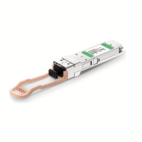
The SPTMBP1PMCDF compatible module serves equipment requiring a 100G QSFP28 interface with 850nm optics and a 70m on OM3 / 100m on OM4 rating. Connection is through MTP/MPO-12/UPC. Product data, application guidance and factory verification are presented together to support structured fiber installations preserve a documented and serviceable optical channel.
OEM Part Number: SPTMBP1PMCDFHT Part Number: QSFP-SR4-100G
Product Highlights
- Compatible alternative to Intel SPTMBP1PMCDF
- 100G connectivity at 103.125Gbps (4x 25.78Gbps)
- Optical wavelength: 850nm
- Specified reach: 70m on OM3 / 100m on OM4
- MTP/MPO-12/UPC / MMF interface
- Digital diagnostic monitoring: Supported
- Operating temperature: 0 to 70°C (32 to 158°F)
Specifications
| HT Part Number | QSFP-SR4-100G |
|---|---|
| Manufacturer | HT |
| Form Factor | QSFP28 |
| Max. Data Rate | 103.125Gbps (4x 25.78Gbps) |
| Wavelength | 850nm |
| Max. Cable Distance | 70m@OM3/100m@OM4 |
| Connector | MTP/MPO-12/UPC |
| Media | MMF |
| Transmitter Type | II-VI VCSEL |
| Receiver Type | PIN |
| TX Power | -8.4~2.4dBm |
| Minimum Receiver Power | -10.3dBm |
| Power Budget | 1.9dB |
| Receiver Overload | 2.4dBm |
| Typical Power Consumption | ≤2.5W |
| Extinction Ratio | >2dB |
| DDM/DOM | Supported |
| Commercial Temperature Range | 0 to 70°C (32 to 158°F) |
| Modulation (Electrical) | 4x 25G-NRZ |
| Modulation (Optical) | 4x 25G-NRZ |
| CDR (Clock and Data Recovery) | TX & RX Built-in CDR |
| Packaging Technology | COB (Chip on Board) Packaging |
| Bit Error Ratio (BER) | 5E-5 |
| MTBF | 30,800,000 Hours (@40°C, 60% CL) |
| Protocols | QSFP28 MSA, SFF-8636, IEEE 802.3bm, CAUI-4 |
Applications and Optical Link Design
Typical deployments include switch-to-switch, switch-to-server and aggregation links inside a data hall or between adjacent equipment rooms. The MTP/MPO-12/UPC interface connects to the specified multimode cabling, and the stated reach depends on fiber grade and link loss. Keep this interface on the matching multimode optical standard rather than connecting it directly to a single-mode wavelength or reach variant.
Before deployment, check the host port type, supported data rate and firmware requirements. The 100G interface configuration must match the remote equipment; sharing a QSFP28 housing alone does not make two transceiver types interoperable.
For this multimode module, confirm fiber grade, modal bandwidth and total loss before commissioning. The 70m on OM3 / 100m on OM4 figure applies only under suitable cabling conditions. Inspect every MTP/MPO-12/UPC mating point and match the remote optical standard.
Intel Compatibility and Factory Testing
Factory verification starts with the expected SPTMBP1PMCDF identity and finishes with an operating host link. EEPROM data, diagnostic visibility and the stated optical parameters are assessed together. Equipment model, hardware revision and software release can be reviewed before dispatch where platform behavior is uncertain.
Optical Acceptance, Diagnostics and Handling
For this model, the specified transmit-power range is -8.4~2.4dBm; the stated optical power budget is 1.9dB. During commissioning, record the host diagnostic readings after the link has stabilized and compare them with those limits. DOM values are useful operational indicators, but they do not replace calibrated optical measurements when a link is marginal. Investigate unexpected loss through connector inspection, cleaning and a channel measurement before replacing the module. Diagnostic monitoring is listed as Supported. Before every insertion, keep dust caps in place until the patch lead is ready, avoid touching the optical end face and use an appropriate inspection and cleaning procedure. Do not look into an active optical interface.
Structured Fiber Pathways and Serviceability
Treat the transceiver as part of the complete channel. Follow the intended patch-panel route, maintain bend control and leave service access around the port. Confirm connector polish and fiber type at every mated pair; a documented service allowance is preferable to excess slack concealed inside a rack. For this model, the principal parameters are data rate 103.125Gbps (4x 25.78Gbps), wavelength 850nm, rated reach 70m on OM3 / 100m on OM4.
Ordering Information
Use SPTMBP1PMCDF as the compatibility cross-reference and QSFP-SR4-100G as the HT ordering identity. Keep other reaches or wavelength directions on separate order lines. Neutral labels, customer packaging and project-specific compatibility review are available on request.
Shipping and Lead Time
Standard configurations normally ship within one to three working days, with production lead times confirmed for larger quantities. International courier, air freight and sea freight are available; customer courier accounts and nominated forwarders are accepted.
Quality Assurance and Packaging
Each SPTMBP1PMCDF compatible module is inspected, powered up and functionally checked before protective packing. Dust caps and individual trays shield the interface during transport. Customer references, rack groups and project packing lists can be added for volume orders.
Frequently Asked Questions
Is this an original Intel transceiver?
No. It is an HT-manufactured compatible alternative for equipment that specifies SPTMBP1PMCDF, not an original Intel-branded module.
Which fiber and connector are required?
Use MTP/MPO-12/UPC with MMF. The specified maximum reach is 70m on OM3 / 100m on OM4, subject to fiber quality and total link loss.
Can it be mixed with another wavelength or reach version?
Only when the two ends share the same optical standard, wavelength plan and supported data rate. Check the exact part numbers and link budget rather than relying only on the module form factor.
